QRP ATU by DF3OS

Hans Steinort DF3OS designed, small QRP antenna tuner and send it to me for tests. It is nice, miniature instrument which I present with pleasure. This ATU was decribed in CQ DL 5/2004.
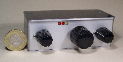
Hans designed his ATU for field day in 2003. It is really tiny; 86x33x70mm. Despite small dimensions provides wide matching range and is equipped with unique LED SWR indicator.
Description.
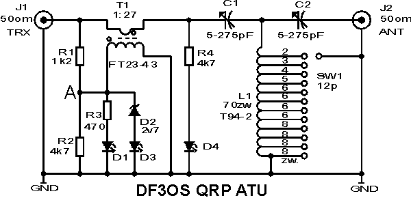
The ATU has typical CLC tuning circuit with two mniature variable capacitors. 5-275pF Plastic dielectric capacitors are applied. The coil has 40uH and is wound on T94-2 toroid. Inductance is adjusted by tap switching with 12-position rotary switch. SWR indicator is worth special attention. It is build from current transformer T1 (1:27 turn ratio, FT23-43 toroid), resistor divider R1/R2 and two-level LED indicator D1, D3. At high amplitude value in the point 'A' both LED glow. Below 4V amplitude, only D3 is lighted. When amplitude falls below appr. 2V, D1 LED turns off also. This way, SWR value changes may be observed and null value of reflected power found. Third LED – D4 - serves as line voltage indicator.


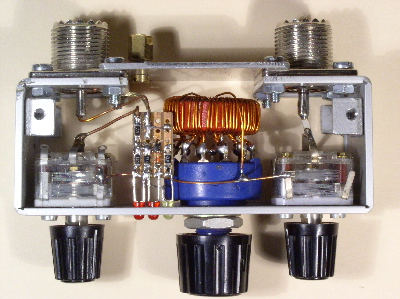
The ATU circuitry is placed in precise shielded enclosure. The body is made from aluminium milled along bending lines. Top and bottom covers are separate parts fixed with M3 screws to the body. All electronic parts fit perfectly inside. The coil is soldered directly to the rotary switch pins. SWR detector is mounted on the small piece of universal board. The current transformer uses very small FT23-43 core. I would probably use the bigger one for easier winding!
Tests.
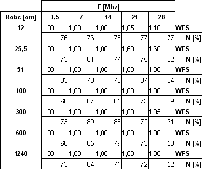
The ATU was tested on resistive load in the range of 12 to 1240ohm, at 5W power, on five amateur bands. It was possible to match the load in all frequency/load combinations and efficiency was quite satisfactory. In a few cases matching was obtained at minimum value of C2 and tuning was very sharp. Some influence of hand attached to the isolated tuning knob was observed. The efficiency of the ATU at low C2 values is lowered, what is typical to CLC high-pass circuit. The general rule is to keep C2 value as high as possible. The table shows SWR and efficiency values for different load values at different frequencies. The circuit was tuned for minimum SWR value measured by external meter at the ATU input.

LED
SWR detector was evaluated as sufficiently accurate. The ATU was
tuned for minimum SWR (both LEDs dark) at different loads and
different frequencies. The SWR controlled on external meter never
exceeded 1:1.5 value, what is very good result for such simple
circuit.
I checked also the ATU with my 18m long LW antenna. On all five bands tuning was easy with low SWR vale at the input. So, I can can fully recommend DF3OS project! It is simple and SWR meter really unique and efficient.
Hans himself agrees, that applying LEDs without reverse voltage protection is doubtful. In practice, however, LED damage had never occur. My mesaurements indicate that amplitude on LEDs are not critical due to limiting action of resistors placed in series and substantial capacitance of LEDs. I think also, that reverse voltage listed in data-sheets is rather the value, at which reverse current is measured, but not the value of LED breakdown.
The problem can be easily solved by reversing the polarity of D1 (with no influence to detector parameters) and adding the detecting diode in parallel with D4.
The original design uses low-current, mid-intensity LEDs. Probably, very high intensity (>1000mcd) red LEDs can provide better sensivity.
Hans sent me his ATU with request to test it and describe in Swiat Radio. His will is also to leave this unit in Poland. It will be one of prizes in autumn QRP contest of SP-QRP Group.
Marcin Swietlinski, SP5JNW, sp5jnw@sem.pl.
February 2007.