Technical Specification
|
Frequency range |
1,8-30MHz |
|
Input power |
10W max |
|
Input impedance |
50om |
|
Matching range* |
30-600om 1,8MHz |
|
|
10-2000om 3,5-14MHz |
|
|
20-1000om 18-30MHz |
|
Efficiency* |
>90% |
|
WFS indicator |
2 LED |
|
Output voltage indicator |
1 LED |
|
Dimensions |
90x80x110mm |
* - pure resistive load
General Description
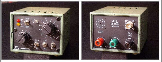
ATL is a simple QRP antenna tuner for matching the unbalanced antennas to standard 50om line. It is based on „L” type matching circuit and resistive SWR bridge with LED null indication. Resistive bridge limits also SWR value at TRX output while tuning random antennas. The radiated power during tuning is limited to 25%.
ATL is compact and consists low-cost components. Properly assebled provides wide tuning range and satisfactory SWR null indication without any calibration.
However dedicated to Long-Wire type antennas it can be also used for SWR correction in coaxial transmission lines.
With additional 50om balun at the input, can be used also with balanced lines.
Circuitry.
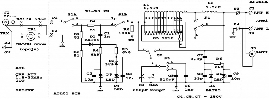
ATL has the simplest „L” matching circuit with switched multitap coil and variable capacitor. Circuit inductance is divided into tapped L1 coil switched by rotary switch S5 and fixed extention coil L2 switched by S4 (L+). Variable capacitor may be connected to input (for Rload<50om) or output (for Rload>50om) with S2 (H/L) switch. Tuning capacitor range may be extended with C5 and C6 capacitors switched by 3-state S3 (C+/C++) switch. SWR bridge consists of R1, R2 resistors in left arm and R3 in series with input impedance of „L” circuit in right arm. The bridge is balanced when input impedance of „L” circuit is equal to 50om. The null indicator is formed by D1/C1 peak detector and two LED D3, D4. Main switch S1 selects signal path directly to antenna (ANT position) or through SWR bridge (SWR position). Output hf voltage can be controlled with peak detector and D6 LED. C7/C8 capacitive divider provides loose coupling to the ATL output .
TR1 50om balun can be optionally instaled at the tuner input.
R6 resistor discharges static electricity induced on the antenna.
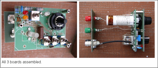
All components except for input and output connectors are placed on single PCB. Additionally screen printed front and back panels are also available. PCB and both panels fit low-cost ABS Z3A housing.

Components.
Coils.
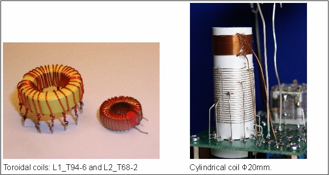
The coils can be winded on two iron-powder toroid cores or on the single plastic coil-former. Taps on L1 provide 1.5x inductance switching steps. The tap numbers in the table below correspond to S5 pin numbers.
The prototype of L1 was winded on 20mm dia. PVC tubing. Nylon string was used in parallel with silver-plated wire to provide appropiate spaceing. Proper string thickness should be choosen to provide overall coil length of 28mm. After wire ends fixing, the string can be removed. The winding require fixing with glue. 3 or 4 thin glue strips along the coil-former will be enough. It is important to leave as much bare wire as possible for taps soldering. Wire connections between PCB and taps should be short and parallel to coil shaft. It leads to fractional turn numbers not exactly corresponding to values in the table but it has neglible influence to circuiot operation. L2 coil is winded in thne same direction, on the same coil-former 10mm above L1.
|
L1 coil (6,5uH). Turns |
||||
|---|---|---|---|---|
|
Tap No |
Amidon T68-6 |
Amidon T94-6 |
Amidon T104-6 |
Φ20mm coil-former |
|
1 |
0 (start) |
0 (start) |
0 (start) |
0 (start) |
|
2 |
1 |
1 |
1 |
1 |
|
3 |
2 |
2 |
2 |
2 |
|
4 |
3 |
3 |
3 |
3 |
|
5 |
4 |
4 |
4 |
4 |
|
6 |
6 |
6 |
5 |
5 |
|
7 |
8 |
8 |
6 |
6 |
|
8 |
11 |
10 |
8 |
8 |
|
9 |
15 |
13 |
10 |
10 |
|
10 |
21 |
20 |
13 |
13 |
|
11 |
31 |
24 |
18 |
18 |
|
12 |
35 |
28 |
22 |
22 |
|
13 |
37 (end) |
30 (end) |
24 (end) |
24 (end) |
|
|
0,4-0,5mm enamelled |
0,4-0,6mm enamelled |
0,4-0,6mm enamelled |
0,4-0,6mm CuAg Coil length 28mm |
|
L2 coil (9,4uH). Turns. |
|||
|---|---|---|---|
|
|
Amidon T68-6 |
Amidon T68-2 |
Karkas Φ20mm |
|
L2 1-2 |
45 |
41 |
21 |
|
|
0,4-0,5mm enamelled |
0,4-0,5mm enamelled |
0,5 enamelled wire by wire |

Capacitors.
Variable capacitor C4 (500pF or 2x250pF) can be air or plastic type. 500pF capacity with additional fixed capacitors C5=510pF and C6=1000pF provide 0-1500pF capacity coverage. If 160m band is not important, 250pF C4 variable with C5=270pF and C6=510pF set can be used to achieve 0-760pF coverage.
With 2x500pF tuning capacitor fixed capacitors C5, C6 can be omitted. One 500pF section is connected permanently as C4, while the second section is connected in place of C5. This way we get two ranges: 0-500pF and 0-1000pF, what is satisfactory in most cases.
Tuning capacitors require extending the shaft. 4mm shaft can be easily extended with 6mm nylon plug. Most of plastic capacitors have very short shafts with M2.5 threaded hole. The only way is to find or make a piece of 6mm rod with threaded hole at one end.
C5 and C6 capacitors must be carefully selected. Mica or ceramic NP0 (C0G) capacitors are the best. The working voltage sholuld be 250V at least. Popular, cheap ferrelectric Z5U or X7R capacitors may lower the efiiciency of the circuit.
Switches.
S1, S2, S3, S4 are popular, miniature toggle switches. Be carefull with the cheapest components! Rather spend some cents more for reliable operation. 12 position rotary switch is available from many suppliers. Remember to remove the ring under the nut to achieve full 12 positions!
Optional Balun.
The simplest balun can be made from RG-174 50om coax and mid-size high permeability ring core. The core and material type is not critical. The goal is to achieve at least 70uH of inductance for 1.8MHz lowest frequency. 11 turns are needed on FT114-43 core.
Optional Surge Arrester.
If surge protection is needed, 250V gas arrester can be mounted directly on output connectors between J3 and J4. The effectiveness of protection depends however of grounding very much.
Assembling.
1. Check if front and rear panel fits the housing. Correct the edges or corners with sand paper if needed.
2. Check if components fit the PCB. Especially the switches and tuning capacitor. Mounting holes for rotary switch and tuning capacitor have to be enlarged.
3. There are many different types of tuning capacitors, so check carefully chosen components with the PCB. There are seven 2.8mm dia. mounting holes on the PCB which may be helpfull. Some components require a little work with the board to make appropriate fitting.
4. Place and solder all small components apart from switches and LED, which must be aligned with front panel first. There are some extra pads under C5, C6 and C7 to match different capacitor sizes.
5. Fix tuning capacitor and solder the terminals to marked pads on the PCB.
6. Put the switches into pad holes. Remove top nut from each one. The lower nut remains under the PCB. Put LEDs in to holes. Join PCB and front panel with three L=15mm, M3 threaded spacers and M3 screws. Now, align LEDs and switches and solder it. The switches must be pushed down to PCB tightly and fixed with nuts before soldering! Rotary switch is kept on PCB by 13 pins, so it's mechanical fixing is not necessary. Plastic bolt near switch shaft can be removed.
7. Wind the coils and solder it on solder side of the PCB. Fix it with glue if needed.
8. Prepare rear panel for connector mounting. Rework the holes to fit choosen connectors. UHF or BNC sockets can be applied and/or screw terminals. Fix the connectors on the rear panel.
9. Connect J1 input connector with P1, P2 pads using RG-174 coax. J1 ground should be soldered to J2 screw terminal with short wire. Ouput terminals J3/J4 are to be connected with thick wire to P3/P4 pads on PCB. J5 connector requires a piece of coax cable to PCB. If the screening is not an issue ordinary wire can be also used.
9. Put all three boards into housing, close it, fix with a screw. Ready!
Z3A housings come in white or black colour. The white one, can be painted according to your need, but some paints are agressive for ABS - be carefull!

Testing.
1. Set S1 switch in SWR position and connect 51om/2-5W loading resistor between J3 and J4. Check DC resistance at J1 input terminal. It should be about 51om for all S2, S3, S4, S5 positions.
2. Switch S1 to ANT position and check again 51om value at the input.
3. Disconnect 51om loading resistor and check if the resistance at the input is equal to 100kom.
4. Set S1 to SWR and put 22.4VDC from power supply to J1. This is equal to 5W HF power. Leave the ATU for a few minutes under power. SWR indicator LEDs should glow.
5. Repeat step 1 and 2 after burn-in test.
6. Connect your TRX to J1 with 50om cable and the antenna to J3 or J5. Try to tune S4 and C4 for maximum receiver noise.
7. Find free frequency and try to tune according to „TUNING” procedure.
TRX and antenna connection.
The connection with TRX requires 50om coaxial cable from J1 to TRX output. Grounding wire have to be connected to J2 terminal. J3 is antenna „hot” terminal for Long-Wire type antennas. J4 is dedicated for counterpoise or ground connection. Coaxial transmission lines can be connected to J5 connector.
If internal balun is applied, it is possible to feed balanced lines connected between J3 and J4. The balun inside, due to it's impedance „cuts” the connection between J2 and J4. While using Long-Wire antenna with weak ground or no ground at all, there is no return path for ground current and tuning may be impossible. In such case short terminals J2(GND) and J4(AL) together. This way, station ground will help to balance antenna current, but sometimes it may cause interferenceces.
Tuning.
The purpose of tuning is to achieve 1:1 SWR (or the lowest SWR possible) at the tuner input. Two LED bargraph indicates SWR bridge balance and thus SWR level. If LEDs do not glow, that means good matching and low SWR value.
Additional output HF voltage indicator helps very little with tuning. Only high impedance antennas provide remarkable glowing. However it indicates any power at the antenna and shows if the load is high or low impedance.
Initial tuning for maximum noise in the receiver mentioned before do not means optimal matching! Proper tuning is possible only with HF power applied but noise peak shows good direction in tuning.
Tuning procedure step by step:
WARNING! Do not switch S1 (SWR/ANT) with HF power applied. It may damage your TRX!
1. Check if TRX and antenna are properly connected.
2. Set S2 to „H” position for high impedance antennas or to „L” for low impedance (very short) antennas.
3. Set S1 to „SWR”.
4. Set tuning capacitor to the middle position.
5. Switch HF power from TX on.
6. Tune the rotary switch to find position with lowest indication on LED SWR indicator. TX can be switched-on permanently. Resistive bridge protects it from excessive SWR.
7. Tune variable capacitor looking for SWR minimum.
8. Switch the inductance one step up and down to check if lower SWR indication can be found.
9. Use C+/C++ switch to extend capacity range or L+ switch to increase inductance if needed,
10. If both LEDs do not glow, the optimal matching was found. Turn TX off and set S1 to ANT position. Your antenna is matched!
Tuning troubleshooting.
If it is not possible to obtain matching:
- Be patient. Tune all combinations of L and C, step by step. Observe slight LED intensity changes and follow them.
- Change the S2 SWR/ANT switch to another position and repeat tuning from the beginnig.
- If random unbalanced wire can not be tuned, change it's length (or counterpoise length), change the grounding.
Part list.
|
Ref |
Type/value |
Qty |
Description |
Comments |
|---|---|---|---|---|
|
R1, R2, R3 |
51om/2W |
3 |
0414 resistor, carbon or thin film |
|
|
R4, R5 |
6k8/0.25W |
2 |
0207 resistor |
|
|
R6 |
100k/0.25W |
1 |
0207 resistor |
|
|
R7 |
1k6/0.25W |
1 |
0207 resistor |
|
|
C1 |
1nF/100V |
1 |
ceramic capacitor |
|
|
C2, C3, C9 |
10nF/50V |
3 |
ceramic capacitor |
|
|
C4 |
2x250pF |
1 |
ceramic capacitor |
|
|
C5 |
510pF/250V |
1 |
mica or NP0(C0G) capacitor |
|
|
C6 |
1000pF/250V |
1 |
mica or NP0(C0G) capacitor |
|
|
C7 |
3.3pF/250V |
1 |
ceramic capacitor |
|
|
C8 |
33pF/50V |
1 |
ceramic capacitor |
|
|
J1 |
BNC 50om |
1 |
coax connector |
or UHF |
|
J2 |
|
1 |
screw terminal |
|
|
J3, J4 |
|
1 |
screw terminal |
|
|
J5 |
UHF |
1 |
coax connector |
|
|
L1 |
6.5uH |
1 |
main coil |
see text |
|
L2 |
9.4uH |
1 |
extension coil |
see text |
|
S1 |
DPDT |
1 |
toggle switch |
12x12mm |
|
S2, S4 |
SPDT |
2 |
toggle switch |
8x12mm |
|
S3 |
SP3T |
1 |
toggle switch |
8x12mm |
|
S5 |
1P12 |
1 |
12 pos. rotary switch (CK1049, CK1059) |
Lorlin... |
|
D1, D5 |
1N4148 |
2 |
high speed diode Vr>50V |
BAT85... |
|
D2 |
3V9 |
1 |
zener diode |
|
|
D3, D4 |
LED Φ5mm |
2 |
high efficient LED |
Vf<2V !!!!!! |
|
D6 |
LED Φ5mm |
1 |
high efficient LED |
Vf<2V !!!!!! |
|
|
RG-174 |
0.2m |
50om miniature coax |
|
|
ATL01 |
|
1 |
PCB |
|
|
ATLP01 |
|
1 |
front panel |
|
|
ATLT01 |
|
1 |
rear panel |
|
|
|
M3/15 |
3 |
spacer, 15mm long, M3 threaded |
|
|
|
Z3A |
1 |
ABS housing |
(Kradex Warszawa) |
Do not apply pure green or hyper red LED due to it's high forward voltage.
Marcin Swietlinski,
SP5JNW, Warszawa, Poland
sp5jnw@sem.pl
Created: 20.04.06.
Mods: 22.04.06,
28.05.06, 29.05.06 coil data, part list
27.10.06 circuit drawing